12 V trigger
JP150PCB 1.4since 26.10.1Jan PřibyslavskýThis page does not apply to the product or PCB revision chosen in the header.
PCB 1.4 has a trigger input for the usual 12 V trigger signal of a preamplifier or source, or for a push button. The firmware offers three modes. On PCB 1.3 the settings are accepted and stored but have no effect.
Modes
| Mode | Behaviour |
|---|---|
OFF (default) |
The input is ignored. |
FOLLOW |
A change to high returns the module to NORMAL; a change to low takes it to the trigger target level. The level found at start counts too: a module started without a trigger powers down about 5 s after start, and switching to FOLLOW applies the current level at once. The encoder and the control interface still override, until the trigger changes again. |
ONOFF |
The input is a push button. A press while powered down wakes the module; a press that begins in NORMAL and is held for one second powers it down. The press that wakes never powers down, and the level found at start is not a press. |
Settings
| Setting | Values | Default |
|---|---|---|
| Mode | OFF, FOLLOW, ONOFF |
OFF |
| Target level | PWRSTAGE_IDLE, PWRSTAGE_OFF, SLEEP, STANDBY |
SLEEP |
| Priority over automatic decisions | on, off | on |
All three settings are stored and survive a power cycle. With the priority on, in FOLLOW mode, the
automatic decisions never contradict the trigger: no silence power-down while the trigger is high,
no audio wake while it is low. With it off, automatic power-down and the audio
wake work as before, beside the trigger.
A new level counts after 0.1 to 0.2 s; shorter pulses change nothing. Nothing is acted on in the first 5 s after start. A SigmaStudio session on the DSP bus and a pending power-stage retry take precedence over the trigger.
In MuraLink
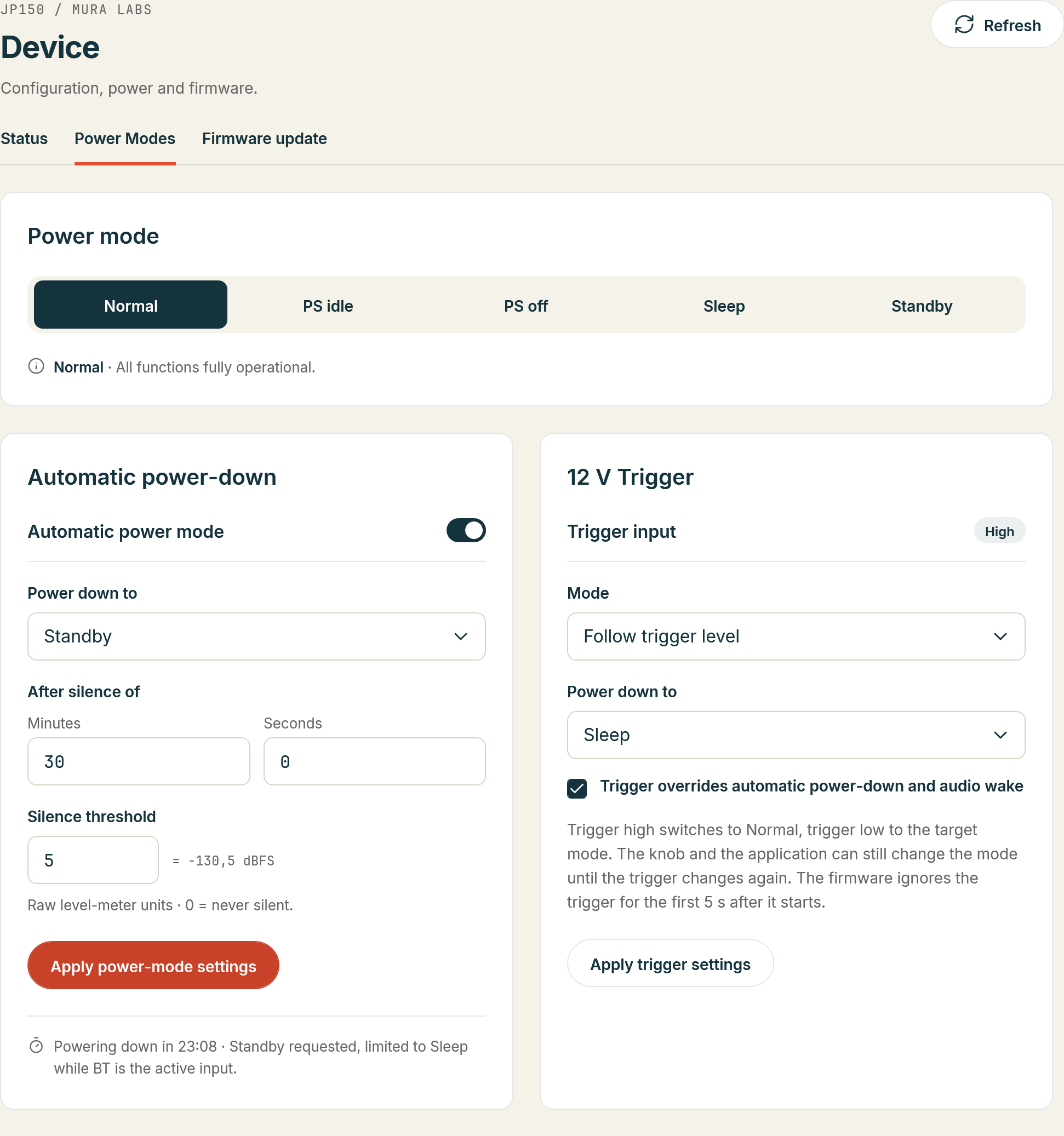
Device > Power Modes, section 12 V Trigger: Trigger input shows the level read at the input, Mode and Power down to set the mode and the target level, and the check box Trigger overrides automatic power-down and audio wake is the priority; Apply trigger settings sends the three to the module. On a board without the input the section is greyed out.
Over the control interface
| Setting | Commands |
|---|---|
| Input level | SYS:TRIG? answers 1, 0, or N/A on PCB 1.3 |
| Mode | SYS:TRIG:MODE?, SYS:TRIG:MODE with OFF, FOLLOW or ONOFF |
| Target level | SYS:TRIG:TARGET?, SYS:TRIG:TARGET with the level |
| Priority | SYS:TRIG:PRIORITY?, SYS:TRIG:PRIORITY with 0 or 1 |
The syntax and the answers are in the SYS:TRIG reference.
Wiring
JST PH, 2 pins (12V TRIGGER): pin 1 trigger, pin 2 GND. 3.3 V to 12 V reads as active; the input has a series resistor and a 3.3 V clamp. See Connectors and pinouts.