Hardware
JP150PCB 1.3PCB 1.4Jan PřibyslavskýThis page does not apply to the product or PCB revision chosen in the header.
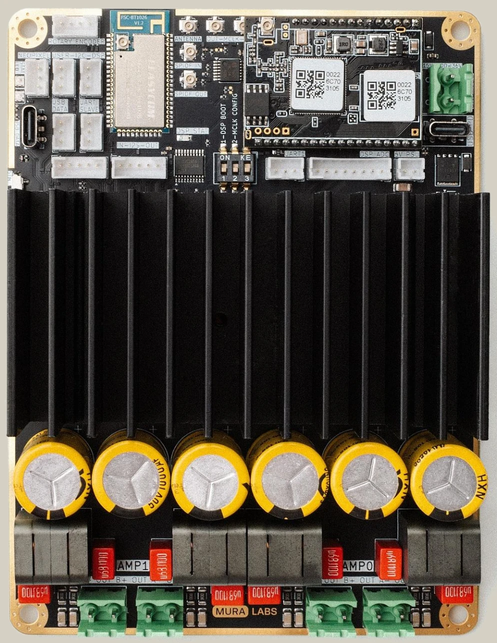
This section describes the board itself: the specifications, every connector with its pinout, the indicators, the configuration, the power levels and the mechanical data, for PCB revision 1.3 and 1.4.
-
Electrical and audio specifications, absolute maximum ratings, environmental limits.
-
Every connector of both revisions with its pinout, and the pin-order changes of PCB 1.4.
-
The power, status and DSP LEDs, the level meter, the special patterns and the extra LEDs of PCB 1.4.
-
Bridging the power stages, the DIP switch of PCB 1.3, the jumpers and settings of PCB 1.4.
-
The five power levels, what each switches off, and the idle currents.
-
Board outline, mounting holes and height.
-
Supply, heat, speaker wiring and handling precautions.