Indicators and LEDs
JP150PCB 1.3PCB 1.4Jan PřibyslavskýThis page does not apply to the product or PCB revision chosen in the header.
The module has a power LED, a status LED, a DSP LED and a six-LED level meter on both revisions. PCB 1.4 adds indicators for the power stages, the Bluetooth module and the USB-C supply.
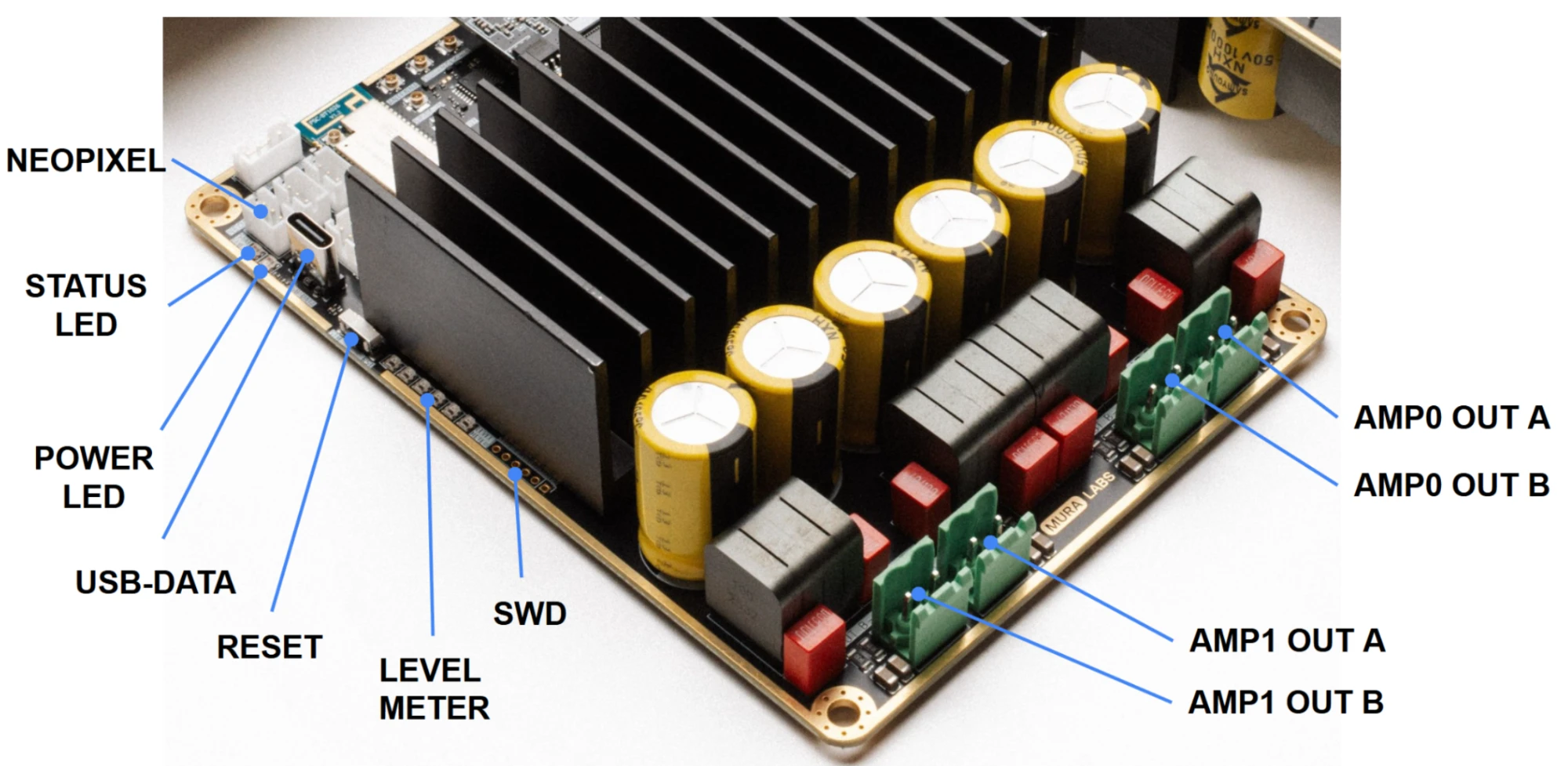
Main indicators
| Element | Function | Behaviour |
|---|---|---|
| Power LED | Power and firmware heartbeat | A low level with a short bright blip once per second while the firmware runs. In any power-down level it goes dark with a short flash every two seconds. |
| Status LED | Input and state | Input colours: blue Bluetooth, white Wi-Fi, magenta USB, cyan I2S, amber S/PDIF, yellow internal 1 kHz sine. Bluetooth and TWS patterns: LED reference. Off in any power-down level, restored on waking. |
| DSP LED | DSP activity | Flashing means the DSP program runs (1 Hz with the default program). Dark in sleep and standby, where the DSP is held in reset. On PCB 1.4 it is driven by the DSP's MP7 pin. |
| Level meter | Signal level of the selected input, ahead of the volume control | Cleared in any power-down level; frozen on its last reading while a SigmaStudio programmer is active. |
Special patterns
| State | Status LED | Level meter |
|---|---|---|
| Unsupported board, safe state since 26.10.1 | Red with a dim white step every second | Dark |
| Fatal error | Red blink | – |
| Update mode and firmware installation | Amber patterns, blue progress, green or red result: see LED indication during updates | Progress bar in blue |
The safe state means the firmware found no factory record it supports on the board (a bare development board, or a record of another product). The outputs stay muted and only the identification and update commands answer; see Start-up and the safe state.
Additional indicators on PCB 1.4 PCB 1.4 only
| Silkscreen | Colour | Meaning |
|---|---|---|
| AMP0 CLIP, AMP1 CLIP | Yellow | The power stage reports clipping. |
| AMP0 FAULT, AMP1 FAULT | Red | The power stage reports a fault (over-temperature, over-current or under-voltage). The decoded fault is readable with AMP0:FAULT? / AMP1:FAULT?. |
| BT LED | Blue, green | The Bluetooth module's own status LEDs. |
| USB C PD | Green | A USB-C power source is connected. |
The power-stage and Bluetooth indicators can be disabled by removing the 0 Ω links marked AMP LED DISABLE and BT LED DISABLE.
Known issue on some PCB 1.4 modules
On part of the first PCB 1.4 production batch the power LED, status LED and level meter show white or random colours after power-on. Audio and control are not affected; a firmware fix is in preparation. See Known issues.