Writing the boot memory
JP150PCB 1.3PCB 1.4Jan PřibyslavskýThis page does not apply to the product or PCB revision chosen in the header.
The DSP loads its program from a boot memory at every power-up and every wake from sleep or standby. The memory differs between the revisions, and so do the SigmaStudio settings to write it.
A 32 Mbit SPI flash on the DSP's own bus. It can be written in three ways:
- With MuraLink, from the firmware update bundle (the default program) or from your own
SigmaStudio self-boot export (
E2Prom.Hex). MuraLink sets the boot read clock and verifies the result. See Boot memory with MuraLink. - From SigmaStudio through the DSP (Hardware Configuration, right-click the ADAU1452 block, Self-boot Memory, Write Latest Compilation through DSP) with the settings below.
- From the control interface with the
DSP:FLASHcommands, which is what MuraLink uses.
SigmaStudio settings for PCB 1.4:
| Parameter | Value |
|---|---|
| Protocol | SPI |
| Memory size | 33554432 bits |
| Page size | 256 bytes |
| Number of address bytes | 3 |
| Write speed | 5000 kHz (this is also the DSP's boot read clock; never below 400 kHz) |
| SPI mode | 3 |
| Instructions | write enable 06, write 02, read 03, chip erase C7 |
| Chip erase cycle time | at least 30 s (60 s for margin) |
Before the write, switch the DSP self boot off and power-cycle; after the write, switch it on
and power-cycle again. The setting is changed over the control interface only (DSP:SELFBOOT
with 0, wait one second, power cycle; afterwards DSP:SELFBOOT with 1, wait one second,
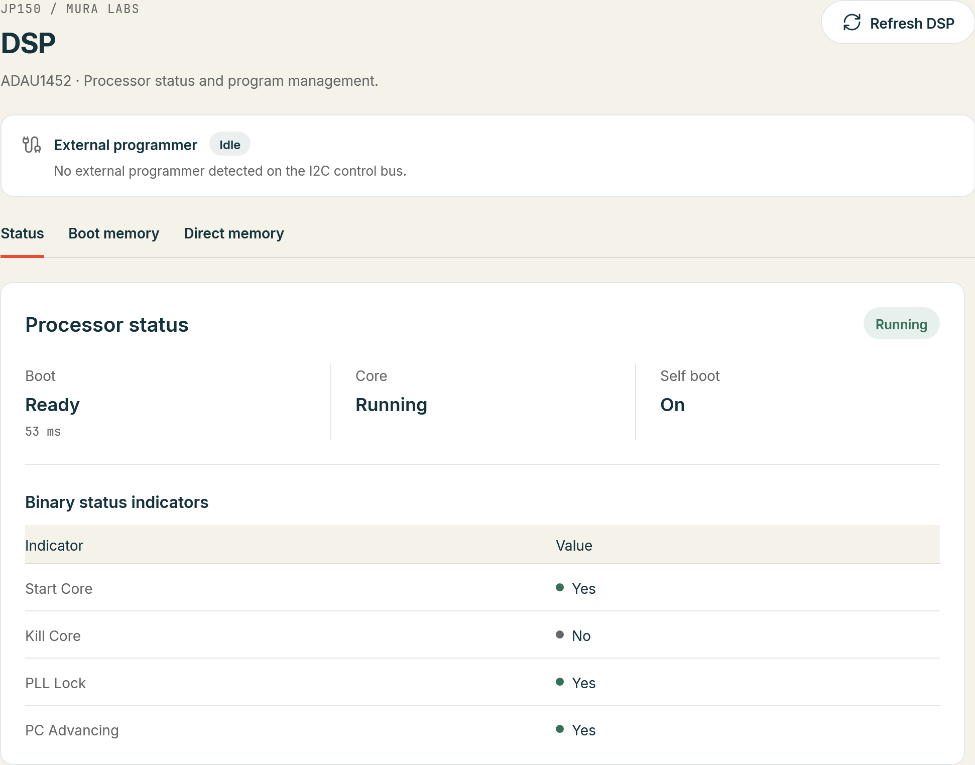
power cycle); MuraLink shows it on DSP > Status as read-only.
Warning
With a chip-erase time shorter than the flash needs, SigmaStudio programs the pages while the flash is still erasing; the flash ignores them and stays blank, and the DSP does not boot. SigmaStudio 4.7 does not always keep changed memory settings: check them before every write. An export made with the PCB 1.3 (I2C) settings does not boot on PCB 1.4.
A 512 kbit I2C EEPROM on the DSP's own bus, written from SigmaStudio through the DSP (Hardware Configuration, right-click the ADAU1452 block, Self-boot Memory, Write Latest Compilation through DSP). DIP switch 1 must be OFF while writing.
| Parameter | Value |
|---|---|
| Protocol | I2C |
| Memory size | 524288 bits |
| Page size | 128 bytes |
| Write speed | 100 kHz |
| Number of address bytes | 2 |
Never use "Write Latest Compilation USB" on PCB 1.3: it writes over the shared bus to address 0xA0, where the module's settings memory sits. An export made with the PCB 1.4 (SPI) settings does not boot on PCB 1.3.
Checking that the program runs
Power the module off, disconnect the USBi, make sure the self boot is on (PCB 1.3: DIP switch 1 ON;
PCB 1.4: the Self boot tile on MuraLink's DSP > Status, or DSP:SELFBOOT? answering 1,1), and
power on. The green DSP LED flashes at 1 Hz with the default program and audio plays on the selected
input. MuraLink's DSP > Status shows the boot outcome and time in the Boot tile and the core state
in Core; DSP:BOOT? answers READY with the boot time.