Specifications
JP150PCB 1.3PCB 1.4Jan PřibyslavskýThis page does not apply to the product or PCB revision chosen in the header.
On this page you find the electrical and audio data of the module and its limits. Unless noted, values apply at 25 °C ambient and nominal supply. Typical values are informative; performance depends on configuration, load impedance, cooling and the DSP program.
Key features
- Two TAS3251 Class-D power stages: 4 × 150 W, 2 × 300 W or 2.1 configurations.
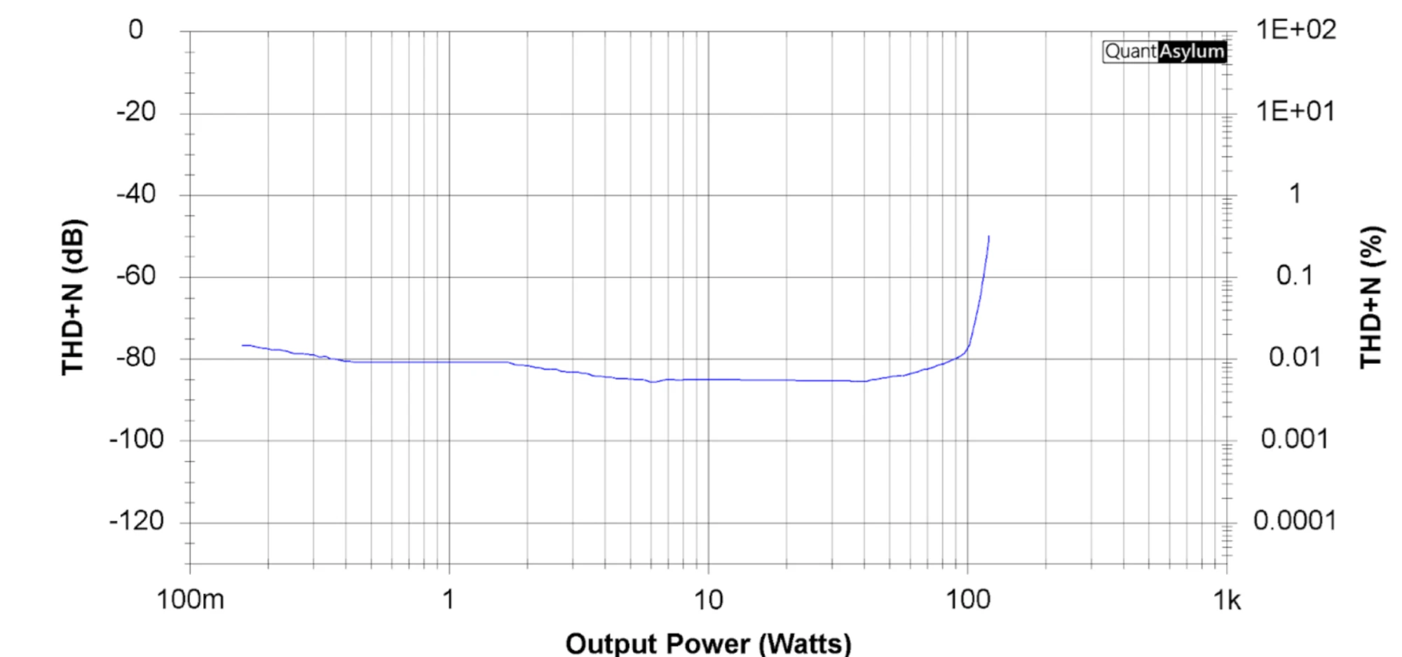
- Typical distortion 0.005 % THD+N at 10 W into 4 Ω and 0.015 % at 100 W into 4 Ω (1 kHz).
- ADAU1452 SigmaDSP, programmable in SigmaStudio, for EQ, crossovers, dynamics and routing.
- Digital inputs up to 96 kHz / 32 bit: I2S and TDM, S/PDIF, USB, Bluetooth, Wi-Fi.
- True Wireless Stereo over Bluetooth, with a remembered partner (TWS).
- Control over UART and USB (virtual COM port) with one command set; MuraLink on Windows.
- Dual power input with automatic selection: DC 15 to 36 V and USB Power Delivery up to 100 W.
- Firmware updates from the PC with MuraLink, installed by the module's own bootloader. since 26.10.1
- Automatic power-down with wake on audio, per-input enable, SigmaStudio programmer coexistence.
- Supply voltage, current and power, MCU and power-stage temperature, per-stage clip, fault and clock reporting.
- PCB 1.4: 12 V trigger input, USB-C power sensing, a second I2S output, DSP boot memory written from the PC, per-stage clip and fault LEDs.
Typical applications
- Active loudspeakers (two- or three-way) with on-board crossovers and equalisation.
- 2.1 and four-channel amplifiers for portable or installed audio.
- Network audio receivers with DSP and high-power amplification.
- A development platform for ADAU1452 SigmaStudio projects with a high-power output stage.
Functional blocks
To be added
A block diagram of the module's internal architecture.
- Audio inputs and outputs. I2S/TDM input and output headers (PCB 1.4 adds a second output), S/PDIF in and out, USB audio, the Bluetooth module and the Wi-Fi module.
- DSP. The ADAU1452 SigmaDSP with its boot memory, an I2C EEPROM on PCB 1.3 and an SPI flash on PCB 1.4, and the SigmaStudio programmer connector (DSP).
- Power amplification. Two TAS3251 devices driving four channels in BTL, or configurable for PBTL and 2.1 (Configuration).
- Control and monitoring. The STM32 host microcontroller with its bootloader and the factory record in its OTP memory; input selection and enabling, DSP control, the power levels with automatic power-down and, on PCB 1.4, the 12 V trigger; the programmer detection, the settings memory, the watchdog, and the monitoring of supply, temperatures and power stages (an INA226 power monitor on PCB 1.4).
- User interface. The encoder, the status, power and DSP LEDs and the level meter; on PCB 1.3 the configuration DIP switch, on PCB 1.4 the clip, fault, Bluetooth and USB-C indicators (Indicators and LEDs).
- Power. DC-IN 15 to 36 V and USB-PD up to 100 W with automatic selection, reverse-polarity protection and inrush limiting; a 5 V output for accessories.
Recommended operating conditions
| Parameter | Min | Typ | Max | Unit | Notes |
|---|---|---|---|---|---|
| DC-IN supply voltage | 15 | – | 36 | V DC | Full output power across the range. Do not exceed 36 V: on PCB 1.4 the supply monitor is specified to 36 V. |
| Input current (DC-IN) | – | – | 20 | A | System-level limit. |
| Idle current at 36 V, normal operation | – | 250 | – | mA | PCB 1.3, Wi-Fi and Bluetooth enabled. See Power levels. |
| Idle current at 36 V, standby | – | 30 | – | mA | PCB 1.3, deepest level. |
| Operating ambient temperature | −10 | – | +60 | °C | Limited by cooling. |
| Power stage switching frequency | 575 | 600 | 625 | kHz | TAS3251 configuration. |
| 12 V trigger input (PCB 1.4) | 3.3 | 12 | 12 | V | Reads as active above the threshold; series resistor and 3.3 V clamp. |
Typical performance
THD+N versus output power at 36 V into 4 Ω (BTL, I2S input, left channel) stays near 0.01 % from 1 W to 100 W and rises steeply at clipping above about 120 W.